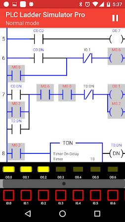
Introduction
- Plc Programming Simulator Online
- Plc Simulator online, free
- Plc Simulator App
- Ladder Logic Simulator
- Video Tutorialsplc Ladder Simulator 2

- PLC Programming Tutorials & Videos PLC Basics What is a PLC? (4 Part Series) (1) Basics of PLCs, featuring the CLICK series. (2) Learn the basics featuring DirectLOGIC Programmable Logic Controllers. (3) Benefits and features of the new Do-more PLC.
- I have recently come across a free virtual plc simulator called PLC Fiddle. It will enable you to create simple PLC ladder logic code within your browser free. This is an ideal way in understanding PLC concepts for industrial automation. All of the basic PLC instructions that come with most plc.
Plc Programming Simulator Online

If by the end of the video you feel like i deserve it, leave a like and consider hitting that Subscribe Button. Thank you!Join our Discord here 🍁 discord.g.
The OSR, also known as One Shot Rising, instruction allows a programmer to create a scenario where an output is energized for a single scan when a transition from a logic low to a logic high is detected on the input side of the instruction. The OSR is identical to the ONS in the performance. However, it does give the programmer slightly more flexibility due to a dedicated output bit. Furthermore, the instruction is also a lot more explicit. It resides on the right side of the ladder logic rung and allows the user to use its output tag where needed within the program.
Example & Usage of OSR
Here’s a real-world scenario of an OSR instruction:
- A Micrologix 1100 Allen Bradley PLC is used to control a process.
- A “Heating Process Start” status is tied to I:0/0.
- The F8:0 register is used to read the temperature of the process.
- The F8:1 register is used to store the initial temperature of the process.
- An OSR Instruction is tied to the output of the“Heating Process Start” XIC instruction.
- The “Output Bit” of the OSR instruction is used on an XIC instruction in rung “0001”
- Once the I:0/0 is pulled HIGH, the OSR is executed once.
- Once the OSR executes, the “Output Bit” is set to HIGH for one scan of the PLC.
- The MOV instruction moves the contents of the F8:0 register to the F8:1 register.
Programming example in RSLogix 500:
Plc Simulator online, free
Outcome:
The OSR instruction is energized by the “Heating Process Start” condition. As soon as this condition is met, the “Output Bit” of the OSR is set to HIGH for a single scan of the PLC. During this scan, the bit allows the MOV instruction to energize through an XIC instruction. The MOV instruction transfers the contents of a register into another at the start of the process.
Data Types Allowed for OSR
The OSR instruction will work with the following data types within the RSLogix 500 environment:
- Boolean – The OSR requires two bits to operate. One is called the “Storage Bit” and the other the “Output Bit”. The “Output Bit” should be the only one used outside of the instruction.
Plc Simulator App
Important Notes
- Note 1 – The OSR instruction requires two non-input boolean bit to function. The “Storage Bit” should not be used anywhere else in the program. The “Output Bit” should be used as a condition to execute other instructions.
Ladder Logic Simulator

Video Tutorialsplc Ladder Simulator 2
Video Tutorial
